
Views: 0 Author: Site Editor Publish Time: 2026-07-24 Origin: Site


The operational success of any municipality or industrial facility relies heavily on the final leg of energy delivery. Bridging the gap between high-pressure interstate transmission and safe, usable end-point consumption requires absolute precision. Aging infrastructure, stringent safety regulations, and fluctuating demand profiles create significant risks for utility managers and industrial planners. Inefficient pressure regulation or outdated pipeline materials lead to costly leaks, compliance failures, and supply disruptions. Designing, upgrading, or evaluating a Natural Gas Distribution System requires a rigorous assessment of infrastructure components, material trade-offs, and modern monitoring technologies. This guide breaks down the technical evaluation criteria for optimizing a secure and scalable gas delivery network, focusing on practical field applications, engineering standards, and physical asset management.
System Architecture: A reliable natural gas distribution system relies on precisely engineered city gates, distribution mains, and service lines to step down pressure from over 1,000 psi to under 0.25 psi.
LDC Custody Transfer: Local Distribution Companies (LDCs) act as the critical operational backbone, taking ownership of the gas at the city gate and managing the localized gas supply network.
Material Selection: Transitioning from legacy steel and cast iron to High-Density Polyethylene (HDPE) in city gas distribution significantly reduces corrosion risks and long-term maintenance costs.
Risk Management: Implementing comprehensive Integrity Management Programs (IMP) and real-time SCADA monitoring is non-negotiable for mitigating leak risks and ensuring regulatory compliance.
Modernization: Upgrading a gas supply network with Advanced Metering Infrastructure (AMI) provides the data granularity necessary for accurate demand forecasting and automated pressure control.
To ensure reliable delivery without over-pressurization, decision-makers must understand the specific success criteria for each stage of the distribution network. The process begins at the transmission interface and ends at the consumer meter. Each component must function flawlessly to maintain system integrity. Field engineers evaluate these systems based on flow capacity, pressure ratings, and mechanical reliability.
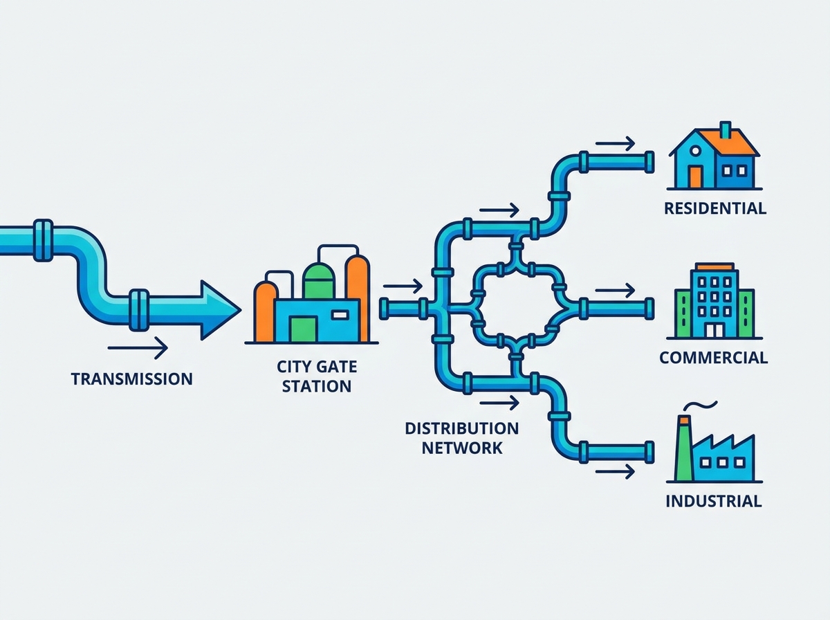
Natural gas travels immense distances from production fields through high-pressure interstate transmission pipelines. These pipelines operate at pressures often exceeding 1,000 psi. Before reaching local consumers, the gas must transition into the local network. Local Distribution Companies (LDCs) manage this custody transfer point. They take ownership of the commodity and assume responsibility for its safe delivery.
Physical underground storage facilities play a vital role in balancing pipeline pressure before local distribution. LDCs rely on depleted reservoirs, aquifers, and salt caverns to store excess gas during low-demand periods. When demand spikes, operators withdraw gas from these storage assets to maintain steady pressure across the distribution grid. Evaluating the proximity, injection rates, and withdrawal capacity of these storage facilities is essential for maintaining a resilient supply chain. Engineers must also account for base gas requirements, which is the volume of gas that must remain in the storage facility to maintain adequate reservoir pressure.
The city gate, or town border station, serves as the primary interface between interstate transmission lines and the local distribution grid. Its primary function is pressure reduction. Transmission line pressures ranging from 200 to 1,500 psi must be stepped down to safer distribution levels. This reduction occurs through a series of heavy-duty pressure regulators and control valves.
City gate infrastructure requires rigorous evaluation based on several operational criteria. First, odorant injection systems add mercaptan to the naturally odorless gas, giving it a distinct smell for leak detection. Second, filtration and scrubbing mechanisms remove particulates, moisture, and pipeline scale that could damage downstream equipment. Finally, primary custody-transfer metering must deliver exceptional accuracy. Operators typically utilize ultrasonic or turbine meters at this stage, paired with gas chromatographs to measure the exact heating value of the incoming gas.
Because dropping pressure rapidly causes a corresponding drop in gas temperature (the Joule-Thomson effect), city gates often employ water bath heaters. These heaters warm the gas before it passes through the regulators, preventing the formation of ice or methane hydrates that could freeze the valves in an open or closed position.
Once past the city gate, gas enters the primary piping infrastructure. A modern gas supply network utilizes a hierarchy of distribution mains. High-pressure mains transport large volumes of gas across broad geographic areas, typically operating between 60 and 100 psi. Medium-pressure mains route the flow into specific neighborhoods or commercial districts. Low-pressure mains deliver gas directly to residential streets, operating at fractions of a pound per square inch.
District regulator stations are strategically placed throughout this network. They step down pressure between the different main classifications. Proper placement ensures consistent flow during peak demand periods. Operators must continuously monitor these stations to prevent over-pressurization events. Strategically located isolation valves allow maintenance crews to shut off specific network segments without disrupting service to the entire municipality.
High-pressure transmission lines feed the city gate.
City gate regulators drop pressure and inject odorant.
High-pressure distribution mains carry gas to regional hubs.
District regulators step pressure down for medium-pressure mains.
Low-pressure mains distribute gas to individual streets.
The final delivery stage connects the distribution mains to residential, commercial, or industrial meters via service lines. These narrow-diameter pipes carry gas directly to the end user. At the termination point, a service regulator reduces the pressure one final time, typically to less than 0.25 psi for standard residential appliances.
Success criteria for service regulators include fail-safe mechanisms and environmental durability. Overpressure protection devices (OPDs) are mandatory components at this stage. If a regulator fails, the OPD vents excess gas safely to the atmosphere or shuts off the flow entirely. Meters must withstand extreme weather conditions while maintaining precise volumetric measurement capabilities. Modern installations also include Excess Flow Valves (EFVs) installed on the service line near the main. If an excavator severs the service line, the EFV automatically trips shut, stopping the flow of gas and preventing a catastrophic release.
Selecting the right materials dictates the lifespan and safety of the network. Engineering decisions made today will impact operational efficiency for decades. Utility planners must balance upfront capital expenditure against long-term reliability and maintenance requirements.
Historically, gas distribution networks relied heavily on bare steel and cast iron pipes. While durable, these legacy materials present severe corrosion risks. Soil corrosivity and moisture degrade bare steel over time, leading to dangerous leaks. Cast iron is susceptible to graphitization and cracking under ground movement or heavy traffic loads. Maintaining these legacy systems requires frequent, labor-intensive interventions, including the installation of cathodic protection systems and regular leak surveys.
Modern networks utilize Medium and High-Density Polyethylene (MDPE/HDPE). These advanced plastics offer superior flexibility and complete resistance to soil corrosivity. They do not rust, scale, or pit. Furthermore, plastic pipes enable trenchless technology installation methods, such as horizontal directional drilling. This significantly lowers installation costs and minimizes surface disruption. The upfront capital expenditure of replacing legacy pipes is easily justified by the long-term reduction in leak-repair and compliance costs.
Material Type | Corrosion Resistance | Installation Method | Primary Use Case |
|---|---|---|---|
Bare Steel / Cast Iron | Low (High risk of degradation) | Open trench excavation | Legacy systems (phasing out) |
Coated Cathodic Steel | High (Requires active monitoring) | Open trench / Welding | High-pressure distribution mains |
MDPE (Medium-Density) | Excellent | Trenchless / Heat fusion | Low-pressure residential lines |
HDPE (High-Density) | Excellent | Trenchless / Heat fusion | Medium-pressure distribution mains |
When joining polyethylene pipes, field crews use heat fusion techniques. Butt fusion and electrofusion create joints that are as strong as, or stronger than, the pipe itself. This eliminates the mechanical fittings that often serve as leak points in older systems.
Designing pressure regulation stations requires a strict framework based on the maximum allowable operating pressure (MAOP). Engineers must size regulators to handle the highest anticipated flow rates without compromising downstream safety. Undersized regulators cause pressure drops during peak winter heating days, leading to pilot light outages and service disruptions. Oversized regulators can suffer from instability and excessive wear on the valve seats.
Scalability is a primary consideration for growing municipalities. Designing modular regulator stations allows utilities to accommodate future residential or industrial expansion. Instead of requiring complete rebuilds, modular stations permit operators to add parallel regulator runs as load growth dictates. This forward-thinking approach optimizes capital deployment and ensures continuous system reliability. Engineers evaluate flow coefficients (Cv) and lock-up pressure characteristics when selecting specific regulator models for these modular skids.
A localized distribution network must be engineered to handle specific regional demand profiles. Engineers must account for alternative fuel integrations and large-scale industrial loads. Accurate planning prevents localized pressure collapses and ensures adequate supply for all customer classes.
Effective city gas distribution requires sophisticated capacity modeling. Operators use hydraulic modeling software to simulate peak hourly loads and seasonal variations. Winter heating spikes represent the most significant stress test for any distribution grid. Engineers must ensure the network can deliver adequate volume when temperatures plummet and residential furnaces run continuously. They calculate Heating Degree Days (HDD) to predict these spikes accurately.
Demand profiles differ drastically across sectors. Residential heating creates sharp morning and evening peaks. Commercial usage remains relatively steady during business hours. Industrial manufacturing and high-volume gas-to-electricity power generation facilities require massive, sustained volumes. Utility planners utilize regional census data and industrial zoning plans to accurately size the distribution footprint. Anticipating where heavy industrial users will locate allows operators to lay high-capacity mains ahead of actual demand.
Analyze historical consumption data to establish baseline loads.
Incorporate weather forecasts and HDD metrics for winter peak modeling.
Review municipal zoning changes to predict future industrial load centers.
Run hydraulic simulations to identify potential pressure bottlenecks.
During extreme cold weather events, pipeline capacity may fall short of demand. Utilities rely on peak shaving operations to bridge this gap. This involves injecting vaporized Liquefied Natural Gas (LNG) directly into the distribution grid. Assessing the technical requirements for LNG vaporization facilities is necessary for winter readiness. Operators must ensure the vaporized gas matches the specific gravity and Wobbe Index of the pipeline gas to prevent appliance malfunctions.
Modern grids must also adapt to emerging alternative fuels. Renewable Natural Gas (RNG) captured from landfills, wastewater treatment plants, or agricultural waste can be injected into the system, provided it meets strict moisture and contaminant standards. Hydrogen blending is another emerging trend. However, operators must carefully evaluate blending limits, as high hydrogen concentrations can embrittle legacy steel pipes and require specialized metering equipment due to hydrogen's lower volumetric energy density.
The highest operational risks in distribution involve gas migration, explosive hazards, and regulatory audits. Mitigating these risks requires proactive maintenance, advanced detection technologies, and strict adherence to federal safety guidelines.
Federal regulations mandate the implementation of a Distribution Integrity Management Program (DIMP). A robust DIMP requires operators to identify threats, evaluate risks, and implement measures to reduce the likelihood of pipeline failures. This includes prioritizing the replacement of aging cast iron and bare steel infrastructure based on risk scoring models that factor in pipe age, leak history, and proximity to populated areas.
Evaluating leak detection technologies is a core component of risk mitigation. Traditional flame ionization units remain effective for walking surveys. However, modern utilities increasingly deploy optical gas imaging (OGI) cameras to visualize fugitive emissions at regulator stations. Acoustic sensors installed on distribution mains can detect the high-frequency hiss of a leak, providing early warning before gas migrates into confined spaces. Laser methane detectors mounted on vehicles or drones allow for rapid surveying of extensive main networks.
The Pipeline and Hazardous Materials Safety Administration (PHMSA) governs MAOP limits and pipeline replacement mandates. Non-compliance results in severe financial penalties and heightened regulatory scrutiny. Utilities must maintain verifiable, traceable, and complete records of all pipeline components, pressure tests, and maintenance activities.
Establishing automated record-keeping systems is a highly effective mitigation strategy. Digitizing maintenance logs ensures audit readiness and eliminates the errors associated with paper-based tracking. Field crews equipped with mobile GIS applications can update asset data in real-time, ensuring the utility maintains an accurate digital twin of its physical infrastructure. This digital twin allows engineers to track the exact location, material specification, and installation date of every valve and pipe segment.
Digitizing the network requires upfront investment but yields exponential returns in safety, efficiency, and labor reduction. Smart technologies transform passive pipes into actively managed energy delivery systems.
Supervisory Control and Data Acquisition (SCADA) systems provide remote monitoring of city gates and district regulators. Operators in a central control room can view real-time pressure, flow rates, and temperature data across the entire grid. This visibility is necessary for identifying abnormal operating conditions before they escalate into emergencies. Remote Terminal Units (RTUs) and Programmable Logic Controllers (PLCs) transmit this data via secure cellular or radio networks.
SCADA automation directly impacts public safety. Automated valve shut-offs reduce emergency response times from hours to seconds. If a pressure sensor detects a catastrophic main break, the SCADA system can automatically close upstream isolation valves, cutting off the fuel source and minimizing explosive hazards. This automated response capability is a definitive success criterion for modern grid management.
Transitioning from automated meter reading (AMR) to two-way Advanced Metering Infrastructure (AMI) modernizes the final link in the supply chain. AMI networks utilize secure radio frequencies or cellular networks to transmit consumption data multiple times per day. This eliminates manual read errors and drastically reduces the labor costs associated with meter reading fleets.
AMI provides immense value beyond billing accuracy. The system can detect unauthorized usage or meter tampering instantly. Furthermore, AMI provides end-users with granular consumption data. Industrial facility managers can use this data to optimize their energy usage, identify inefficiencies, and reduce operational overhead. Utilities can also use aggregated AMI data to refine their hydraulic models and improve the accuracy of their demand forecasting.
An optimized natural gas distribution system requires a balanced investment in modern, corrosion-resistant materials, stringent safety protocols, and digital monitoring infrastructure. Relying on legacy components in a modern energy landscape invites unacceptable levels of risk and inefficiency. Upgrading physical assets while deploying smart grid technologies ensures long-term operational stability.
Conduct a comprehensive physical audit of current pipeline materials, prioritizing the identification of bare steel and cast iron segments.
Consult with a specialized pipeline engineering firm to model future demand based on regional growth projections and industrial zoning.
Draft a phased modernization roadmap that schedules the replacement of high-risk assets with HDPE piping.
Implement a SCADA integration plan to automate pressure monitoring and remote valve operation at all district regulator stations.
A: Transmission involves moving large volumes of gas over long distances at high pressures (often over 1,000 psi) using wide-diameter steel pipes. Distribution is the localized delivery system that steps down this pressure and routes the gas through smaller mains and service lines directly to end-user appliances.
A: An LDC is a local utility entity that takes ownership of natural gas at the city gate. Its role is to safely manage, maintain, and operate the local distribution network, ensuring reliable delivery and accurate metering for residential, commercial, and industrial customers within a specific geographic area.
A: The network uses a series of mechanical pressure regulators. City gates step down transmission pressure to distribution levels. District regulators further reduce pressure between high, medium, and low-pressure mains. Finally, service regulators at the customer meter reduce the pressure to safe, usable levels for appliances.
A: While legacy systems used bare steel and cast iron, modern networks predominantly use High-Density Polyethylene (HDPE) and Medium-Density Polyethylene (MDPE). These advanced plastics are highly flexible, completely resistant to soil corrosion, and allow for cost-effective trenchless installation methods.
A: Liquefied Natural Gas (LNG) is used for peak shaving during extreme demand periods, such as severe winter weather. Utilities store LNG in specialized tanks. When pipeline supply is insufficient, the LNG is vaporized back into a gas and injected directly into the distribution grid to maintain system pressure.
A: DIMP is a federally mandated safety program requiring gas operators to identify and mitigate risks to their distribution pipelines. It involves evaluating threats like corrosion, excavation damage, and material failure, and implementing proactive maintenance and replacement strategies to prevent leaks and ensure public safety.


