
Views: 0 Author: Site Editor Publish Time: 2026-07-24 Origin: Site


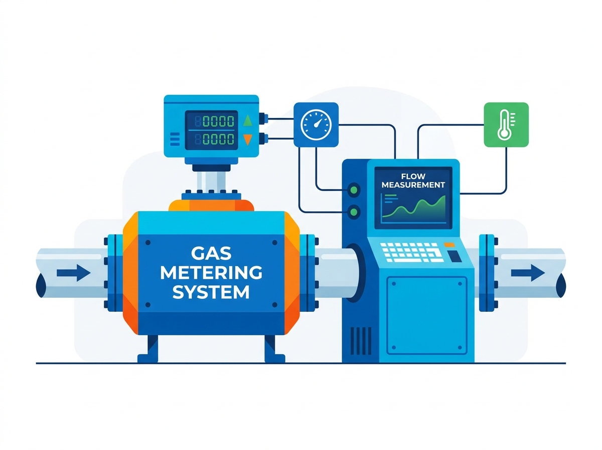
Measurement uncertainty in industrial gas operations carries severe operational consequences. A single percentage point of error in gas measurement can result in massive volume discrepancies or process inefficiencies over a facility's lifecycle. Facility managers, utility coordinators, and pipeline operators must balance strict custody transfer regulations, complex fluid dynamics, and environmental compliance against the operational demands of upgrading measurement infrastructure. We rely on accurate data to keep plants running safely and efficiently. This guide provides an evidence-based framework for evaluating, selecting, and implementing the correct Gas Metering System architecture based on specific industrial use cases, flow profiles, and regulatory demands. You will learn how to match meter types to field conditions, avoid common installation pitfalls, and ensure your measurement data holds up to regulatory scrutiny.
Application Dictates Technology: There is no universal solution; selecting the right meter requires matching the specific gas flow metering technology (e.g., Ultrasonic, Coriolis, Turbine, Thermal) to the facility's unique flow rates, pressure, and gas composition.
Custody Transfer vs. Submetering: Systems used for financial billing (custody transfer) require stringent, legally certified accuracy, while internal cost allocation (submetering) and process control focus on repeatability and cost-efficiency.
System Integration is Critical: A reliable gas metering system relies equally on the primary measurement device, physical conditioning (filtration, regulation), and secondary electronics (flow computers, SCADA telemetry) to ensure data integrity.
Custody transfer applications demand the highest level of measurement certainty because they directly govern volume transactions during gas ownership transitions and custody receipts. In these scenarios, the primary objective is high-accuracy measurement. Requirements for fiscal metering are exceptionally stringent, typically mandating accuracy limits of ±0.5% or better. To achieve and maintain this precision, systems must adhere to legal metrology certifications such as those outlined by AGA, ISO, or OIML. These setups often incorporate redundant sensors to cross-verify readings in real-time and utilize tamper-proof sealing to prevent unauthorized adjustments that could alter volume outcomes.
Internal gas submetering serves a different operational purpose. Instead of facilitating external volume transactions, submetering focuses on allocating utility consumption among different departments, production lines, or tenant facilities within a single enterprise. The success criteria here shift from absolute legal accuracy to medium accuracy and high repeatability. Integration capabilities become paramount. Submeters must communicate seamlessly with existing building management systems (BMS) or energy management platforms. Low footprint installations are preferred to minimize facility modification requirements, allowing operators to retrofit meters into existing piping networks without extensive downtime.
For process control and monitoring, the metering objective is operational stability. These applications require real-time flow control, burner fuel ratio optimization, and rapid leakage detection to maintain safe and efficient plant operations. The requirements include high repeatability, exceptionally fast response times, and durability. Meters deployed in process control often operate in harsh environments, handling untreated or corrosive gas streams where delicate fiscal meters would quickly fail. Robust construction and the ability to maintain consistent readings under fluctuating process conditions define success in this category.
Application Type | Primary Objective | Accuracy Requirement | Key Features Needed |
|---|---|---|---|
Custody Transfer | Fiscal measurement and ownership transition | Very High (±0.5% or better) | Legal certification, redundancy, tamper-proof seals |
Internal Submetering | Departmental allocation and monitoring | Medium (±1.0% to ±2.0%) | BMS integration, compact footprint, easy retrofit |
Process Control | Real-time operational stability | Repeatability over absolute accuracy | Fast response time, rugged construction, corrosion resistance |
Validating compliance requires adherence to established industry standards that govern meter design, installation, and operation. Identifying and applying the correct standard is non-negotiable for system validation. Key frameworks include the American Gas Association (AGA) reports, specifically AGA Report No. 3 for orifice meters, No. 7 for turbine meters, No. 9 for ultrasonic meters, and No. 11 for Coriolis meters. Additionally, the API Manual of Petroleum Measurement Standards and ISO 5167 provide rigorous guidelines for differential pressure measurement. Compliance with these standards ensures that the measurement data holds up under regulatory scrutiny and third-party audits.
Positive displacement meters measure volumetric flow rate by isolating and transporting discrete, physical volumes of gas through flexible diaphragms or rotating impellers. As the gas fills and empties these internal chambers, the mechanical movement translates directly into a volume reading. This technology is best suited for low flow rates, high turndown requirements, and installations where upstream piping straight runs are highly restricted or completely unavailable. Positive displacement meters are susceptible to physical damage from dirty or wet gas. The moving mechanical components require routine lubrication, inspection, and maintenance to prevent jamming or accuracy drift over time.
Turbine meters operate on the principle that gas velocity drives a multi-blade rotor positioned within the flow stream. The rotational speed of this rotor is directly proportional to the volumetric flow rate. These meters excel in steady, medium-to-high flow rates within dry, clean gas pipelines, making them a staple in transmission lines. Turbine meters require significant straight pipe runs or flow straighteners upstream to ensure a uniform velocity profile. Because they rely on moving parts, they are subject to bearing wear. Sudden pressure surges or liquid slugs can cause catastrophic mechanical failure, requiring immediate repairs and system downtime.
Transit-time ultrasonic meters measure the difference in travel time between high-frequency acoustic signals sent upstream and downstream across the gas flow. The time differential is used to calculate the gas velocity and, subsequently, the volume. Ultrasonic meters are highly favored for high-volume custody transfer, zero-pressure-drop requirements, wet or dirty gas handling, and bidirectional flow paths. Since they lack moving parts, maintenance is minimal. They can be sensitive to high-frequency acoustic noise generated by nearby pressure-control valves, which can interfere with the acoustic signals if not properly mitigated.
Coriolis meters force the process gas through vibrating internal tubes. As the gas flows, it causes an inertial phase shift in the vibration, which the meter measures to calculate direct mass flow. This technology is unparalleled for applications requiring direct mass measurement, varying gas compositions, and high-accuracy limits without the need for external pressure or temperature compensation. They are highly versatile across different fluid types. The main drawbacks include a significant pressure drop across the internal flow tubes, which requires more energy to push the gas through the system. There are also physical size and weight limitations, making them impractical for very large diameter pipelines.
Thermal dispersion meters measure the heat dissipation rate of a heated sensor placed directly in the gas stream. As gas flows past the sensor, it carries away heat; the rate of cooling is proportional to the mass flow. This method is highly effective for low-pressure applications, greenhouse gas emissions tracking, stack gas monitoring, and air or biogas applications. They offer excellent sensitivity at low velocities. Thermal dispersion meters are highly sensitive to changes in gas composition. Moisture condensation on the sensor element can cause severe measurement errors, limiting their reliability in wet gas applications.
Vortex shedding meters utilize a bluff body placed in the flow path to create alternating vortices. The meter measures the frequency of these shed vortices, which correlates directly to the flow velocity. This technology is highly robust, making it ideal for high-velocity, high-temperature gas and steam flows where mechanical parts cannot survive. They offer a wide rangeability and require minimal maintenance. The primary limitation is their ineffectiveness at extremely low flow velocities. Below a certain Reynolds number, vortex shedding ceases entirely—a phenomenon known as vortex drop-out—rendering the meter incapable of measuring low flows.
Meter Technology | Best Application | Primary Limitation |
|---|---|---|
Positive Displacement | Low flow, tight installations | Vulnerable to dirty/wet gas |
Turbine | Steady, clean transmission lines | Requires long straight pipe runs |
Ultrasonic | High-volume, bidirectional flow | Sensitive to acoustic valve noise |
Coriolis | Direct mass measurement | High pressure drop, size limits |
Thermal Dispersion | Low-pressure, flare gas | Sensitive to moisture condensation |
Vortex Shedding | High-velocity, high-temperature | Vortex drop-out at low flows |
Accurate measurement begins long before the gas reaches the primary meter. Upstream conditioning and filtration are critical for protecting downstream gas measurement equipment from liquids, pipeline scale, and particulates. Coalescing filters and separators are deployed to strip out moisture and solid contaminants that could damage delicate sensors or mechanical rotors. Flow conditioners are installed to eliminate swirl and restore symmetrical flow profiles. In tight piping footprints where ideal straight runs are impossible, flow conditioners ensure the gas enters the meter with a uniform velocity, preventing significant measurement errors.
Maintaining a stable operating environment is essential for accurate volumetric conversion. Active pressure regulators are utilized to mitigate pressure fluctuations, ensuring the gas maintains a stable operating density as it passes through the meter. Uncontrolled pressure spikes can distort readings and damage equipment. Alongside regulation, safety mechanisms are strictly enforced. Slam-shut valves are integrated into the architecture to automatically isolate the system during high-pressure or low-pressure emergency events. This rapid isolation protects the metering station from catastrophic over-pressurization and prevents hazardous leaks.
The metering run is the core physical segment where the actual measurement occurs. It consists of the primary flow element, which is the calibrated meter body itself. To ensure operational flexibility and safety, the run includes specialized double block and bleed (DBB) valves. These valves allow operators to isolate, vent, and validate the meter safely without shutting down the main pipeline. Bypass lines are also constructed parallel to the main metering run. These bypasses ensure continuous gas supply to downstream processes during scheduled calibration, proving, or emergency maintenance of the primary meter.
The physical meter only provides raw data; secondary instrumentation translates this into actionable, standardized metrics. Flow computers and volume correctors serve as the computing units, performing real-time Pressure, Temperature, and Compressibility (PTZ) calculations to convert actual flowing volume to standard volume. Gas chromatographs (GC) and analyzers are often integrated to determine the exact chemical composition, relative density, and heating value required for energy-based calculations. Telemetry and SCADA outstations use encrypted communication modules to transmit real-time custody and diagnostic data securely to the central control room.
Selecting the right metering technology requires a deep understanding of the specific gas composition and fluid dynamics at the installation site. Operators must evaluate the gas profile to determine if it is dry or wet, and identify any corrosive impurities such as hydrogen sulfide or carbon dioxide. The rise of multi-component mixtures, including hydrogen blending, introduces new challenges for density and acoustic velocity calculations. Determining the exact impact of operating pressures and temperatures on gas density and compressibility is vital. Meters calibrated for low-pressure natural gas will perform poorly if subjected to high-pressure, mixed-composition streams without proper dynamic compensation.
The turndown ratio represents the operational flexibility of the meter, defined as the ratio between the maximum and minimum expected flow rates. Understanding this range is critical for sizing the system correctly. If a meter is oversized, it risks low-flow measurement drop-off, where the gas velocity falls below the sensor's detection threshold. Undersizing the meter can lead to high-flow over-speeding, which causes severe damage to mechanical meters and creates unacceptable pressure drops across static meters. The selected technology must comfortably encompass the facility's entire operational flow range under all seasonal and production conditions.
A common pitfall in system selection is relying solely on idealized laboratory calibration curves. Operators must differentiate between laboratory accuracy and real-world installed uncertainty. In a controlled lab, a meter may achieve ±0.1% accuracy. Once installed in the field, this accuracy is heavily influenced by external factors such as pipeline vibration, upstream piping profiles, and extreme ambient temperature swings. Evaluating how a specific technology responds to these real-world disturbances ensures that the final installation meets the required performance targets without unexpected measurement drift.
Hydraulic disturbances pose a significant risk to measurement accuracy. Upstream headers, reducers, elbows, and control valves cause severe velocity profile distortion and swirl. If gas enters the meter in this chaotic state, the resulting measurement will be highly inaccurate. The primary mitigation strategy involves adhering strictly to AGA and ISO straight-run guidelines during the design phase. When space constraints prevent adequate straight pipe lengths, engineers must install profile-restoring flow conditioners directly upstream of the meter to artificially straighten the flow and eliminate swirl.
Industrial metering stations are frequently exposed to harsh environmental and site-specific factors. Ambient thermal extremes can cause electronic components to fail or alter the physical dimensions of mechanical meter bodies. Heavy pipeline vibration from nearby compressors can introduce noise into Coriolis or ultrasonic signals. Localized acoustic noise from pressure reduction valves can completely blind ultrasonic meters. Mitigation requires implementing specialized environmental protections, including heavy-duty thermal insulation, vibration dampening pipe supports, and acoustic silencers to isolate the gas flow metering equipment from external interference.
As metering systems become increasingly digitized and connected to central networks, data vulnerability emerges as a critical risk. Unauthorized configuration changes on flow computers or intercepted metrology packets can manipulate custody transfer data, leading to massive volume discrepancies or operational hazards. Mitigating cyber-physical threats requires a robust security architecture. This includes implementing multi-level password protection on all local devices, utilizing read-only hardware lockouts for metrology switches, and deploying encrypted SCADA protocols to ensure data cannot be intercepted or altered during transmission.
Determine the exact regulatory and accuracy target required for your specific application, distinguishing clearly between custody transfer and internal process control.
Filter your technology options based strictly on fluid properties, including moisture content, corrosivity, and expected pressure ranges.
Conduct a thorough site survey to identify piping constraints and environmental hazards before finalizing the station layout.
Specify the necessary upstream conditioning equipment, such as flow straighteners and coalescing filters, to protect the primary meter.
Implement robust cybersecurity protocols on all secondary instrumentation and SCADA connections to protect measurement data integrity.
A: Actual volume is the physical space the gas occupies under current pipeline pressure and temperature. Standard volume corrects this measurement to a standardized baseline pressure and temperature using flow computers. This correction is necessary because gas is highly compressible, and standardizing the volume ensures accurate calculations regardless of pipeline conditions.
A: Straight pipe runs allow chaotic, swirling gas flows caused by valves and elbows to stabilize into a uniform, symmetrical velocity profile. Most gas meters require this uniform profile to measure accurately. If straight runs are insufficient, flow conditioners must be installed to artificially straighten the gas flow before it enters the meter.
A: This depends entirely on the meter's turndown ratio. While technologies like ultrasonic and Coriolis meters offer high turndown ratios capable of handling wide flow variations, mechanical meters have narrower operational bands. If the flow range exceeds a single meter's capability, a dual-run metering station with switching valves is typically required.
A: Moisture and liquid drop-out can severely impact accuracy. In thermal meters, moisture alters the heat dissipation rate, causing false readings. In mechanical meters, liquids can wash away lubricants or damage moving parts. Upstream coalescing filters and separators are critical for removing moisture before the gas reaches the measurement equipment.
A: A flow computer is a specialized industrial processor that receives raw flow data from the meter alongside real-time pressure and temperature inputs. It uses complex algorithms to continuously calculate gas compressibility and convert the actual flowing volume into standardized volume or mass, which is strictly required for custody transfer and regulatory compliance.


