
Views: 0 Author: Site Editor Publish Time: 2026-07-24 Origin: Site


Controlling gas pressure involves high operational stakes. Improper selection of a Gas Pressure Reduction Unit leads to process inefficiencies, catastrophic system failures, and severe safety hazards. Engineers often face the complex task of matching dynamic system requirements with exact mechanical specifications. You must account for fluctuating inlet pressures, varying flow demands, and specific gas properties. Relying solely on pipe size rather than actual flow data remains a common and costly engineering error.
We need a systematic, evidence-based framework to evaluate and size these critical components. Specifying the exact unit required for industrial, high-purity, or commercial applications demands precision. You must look beyond basic dimensions and understand the thermodynamic and mechanical realities of your system. This guide provides the technical foundation to evaluate, size, and specify the correct unit for your specific application.
Sizing Requires Flow Data, Not Pipe Size: Accurate specification depends on calculating the required Flow Coefficient (Cv) based on actual minimum and maximum flow rates, not matching the existing line size of the pressure reducing equipment.
Functional Distinction is Critical: Ensure the process calls for a pressure-reducing regulator (controlling downstream pressure) rather than a backpressure regulator (controlling upstream pressure) before evaluating mechanical designs.
Supply Pressure Effect (SPE) Dictates Staging: Single-stage units are sufficient for stable inlet pressures or highly tolerant processes; two-stage units are mandatory for fluctuating supply sources (like gas cylinders) requiring precise outlet control.
Flow Curves Predict Real-World Performance: Evaluating a unit's flow curve is critical to understanding "droop" and "lock-up" behaviors, helping to avoid operating within the unstable choked flow region.
Venting and Relieving Configuration Affects Safety: Specifying self-relieving vs. non-relieving modules dictates how downstream over-pressurization is handled, especially when dealing with hazardous, toxic, or flammable media.
Material Compatibility Extends Beyond the Gas: Selection must account for both the chemical compatibility of wetted parts with the media and the thermal implications of pressure drops (e.g., the Joule-Thomson effect).
You must first clarify the functional difference between regulator types. Pressure-reducing regulators control downstream pressure (P2). They do this by closing as the downstream pressure rises. Conversely, backpressure regulators control upstream pressure (P1). They open as the upstream pressure rises to relieve excess system pressure.
Integrating the wrong class of pressure reducing equipment causes immediate system failure. If you install a backpressure regulator where a pressure-reducing one is needed, the downstream process will starve or over-pressurize. Understanding this directional flow control is the mandatory first step in specification. Field technicians frequently encounter systems where a backpressure valve was mistakenly installed to protect a downstream vessel, resulting in erratic flow and constant venting. Always verify the primary control variable: are you protecting the supply line or feeding the process?
Accurate specification requires documenting the maximum and minimum inlet pressures (P1). You must ensure the selected unit's maximum inlet rating exceeds the highest possible supply pressure. A system spike should never exceed the structural limits of the regulator body. We recommend following a strict sequence to capture these parameters:
Record the absolute maximum supply pressure from the source (e.g., a full cylinder or bulk tank rating).
Determine the minimum supply pressure before the system requires a changeout or shutdown.
Define the required outlet pressure range (P2) and the acceptable tolerance for deviation.
Calculate the maximum, minimum, and nominal flow rates required by the downstream process.
These flow parameters dictate the physical sizing of the internal orifice. Without them, you are guessing. A unit sized for maximum flow might fail to control accurately at minimum flow, leading to seat chatter and premature wear.
Identify the specific gas moving through the system. You must know if the media is inert, corrosive, toxic, flammable, or oxidizing. This chemical profile dictates every material choice inside the unit. For example, oxygen service requires strict cleaning protocols to remove all hydrocarbons, preventing spontaneous combustion.
Determine the required purity levels. Industrial grade applications differ vastly from ultra-high purity (UHP) requirements. UHP systems require specific manufacturing, cleaning, and testing standards to prevent contamination. Assess the specific gravity and molecular weight of the gas. These physical properties directly impact flow capacity calculations and thermodynamic behavior.
Gas Category | Typical Examples | Primary Specification Concerns |
|---|---|---|
Inert | Nitrogen, Argon, Helium | High flow capacity, Joule-Thomson cooling effects. |
Flammable | Hydrogen, Methane, Propane | Non-relieving designs mandatory, strict leak integrity. |
Corrosive | Hydrogen Chloride, Chlorine | Exotic alloys (Hastelloy, Monel), frequent maintenance cycles. |
Oxidizing | Oxygen, Nitrous Oxide | Absolute removal of combustible lubricants, specialized cleaning. |
Single-stage units drop pressure in one mechanical step. They are ideal for applications with constant supply pressure and high flow requirements. However, they are highly susceptible to the Supply Pressure Effect (SPE). As the source cylinder depletes, the outlet pressure will inadvertently rise. This makes them unsuitable for processes requiring tight tolerance over long durations without manual adjustment.
Integrating two reduction stages within a single gas regulator module mitigates SPE. Two-stage units provide a flat, consistent delivery pressure even as supply cylinders deplete. The first stage handles the fluctuating inlet, feeding a stable pressure to the second stage. This improves accuracy but increases the physical footprint and internal complexity. When specifying for analytical instrumentation or precise dosing, the two-stage architecture is non-negotiable.
Spring-loaded mechanisms are standard for applications requiring manual adjustment. A physical spring applies force against the sensing element. While reliable, they suffer from spring rate limitations. They are sensitive to vibration and often exhibit noticeable droop under high flow conditions. The mechanical nature of the spring means the force applied changes slightly as the spring compresses or extends.
Dome-loaded mechanisms excel in high-flow, highly dynamic systems. They use a pilot fluid or gas instead of a mechanical spring to set the pressure. This design improves accuracy and minimizes droop. It also allows for automated or remote setpoint adjustments, making them ideal for complex process control. By utilizing a proportional pressure controller to feed the dome, you can achieve highly responsive, closed-loop pressure management.
Self-relieving designs feature integral relief vents. They exhaust excess downstream pressure directly to the atmosphere. These are ideal for inert gases and applications requiring frequent downward setpoint adjustments. The internal vent allows the system to shed pressure quickly when the operator backs off the control knob.
Non-relieving designs are mandatory for hazardous, toxic, corrosive, or flammable gases. You cannot vent dangerous media into the immediate environment. These designs require dedicated vent piping and external containment systems to manage over-pressurization safely. If you use a non-relieving regulator and need to lower the setpoint, you must flow gas through the downstream system to bleed off the excess pressure.
You must read manufacturer flow curves to predict performance under actual operating conditions. These charts plot outlet pressure against flow rate. They reveal how the unit behaves as demand changes. Never rely on a single maximum flow number; you must see the curve to understand the operational reality.
Droop is the loss of outlet pressure as flow increases. You must establish acceptable droop thresholds for your specific application. Lock-up is the pressure rise above the setpoint required to completely shut off flow under zero-flow conditions. High lock-up causes downstream pressure creep. Avoid the choked flow region on the curve. Operating here causes erratic control, seat chatter, and premature wear. When the valve opens too far, it loses the ability to regulate, acting more like an open pipe than a control device.
Calculating the required Flow Coefficient (Cv) is non-negotiable. Use the standard framework based on gas specific gravity, temperature, inlet pressure (P1), and outlet pressure (P2). The Cv value represents the volume of fluid that passes through the unit at a specific pressure drop. It is the universal metric for valve sizing.
Oversizing a unit is dangerous. It leads to hunting, instability, rapid cycle wear, and seat damage. The valve operates too close to the seat, causing chatter. Undersizing results in the inability to meet downstream demand. This starves processes and causes severe pressure drops during peak usage. Always calculate Cv for your minimum, normal, and maximum flow conditions to ensure the selected unit operates in its optimal control range.
SPE is the inverse relationship where a decay in inlet pressure causes a rise in outlet pressure. It also works in reverse. Understanding this phenomenon is critical for cylinder-fed systems. The unbalanced forces on the main valve poppet cause this shift.
For example, if a standard nitrogen cylinder decays from 2000 psi to 500 psi, a single-stage regulator with a 1% SPE will see a 15 psi rise in outlet pressure. If your process cannot tolerate this drift, you must specify a two-stage module to absorb the inlet fluctuation. Calculating the exact SPE impact allows you to make an informed engineering decision rather than guessing at the required architecture.
Selecting the right wetted materials prevents catastrophic failure. Body materials must match the gas profile. Brass works well for inert and industrial gases. 316L Stainless Steel is required for corrosive or UHP media. Extreme environments, like wet chlorine or sour gas, demand Monel or Hastelloy. Using brass in an ammonia system, for instance, will result in rapid stress corrosion cracking and explosive failure.
Soft seat and seal materials require equal scrutiny. You must evaluate PTFE, PCTFE, PEEK, Viton, and Buna-N against gas compatibility, temperature limits, and permeability. A seat material that swells or degrades in the presence of the process gas will immediately compromise the regulator's ability to lock up.
Material | Common Applications | Key Limitations |
|---|---|---|
Brass | Inert gases, air, standard industrial | Not suitable for corrosive media |
316L Stainless Steel | Corrosive gases, UHP systems | Heavier, harder to machine |
PTFE (Teflon) | Broad chemical compatibility, soft seating | Cold flow under high pressure |
PCTFE (Kel-F) | High pressure, excellent sealing | Stiffer than PTFE, requires higher closing force |
Viton (FKM) | High temperature, oxygen service | Poor low-temperature flexibility |
Rapid gas expansion during pressure reduction causes a thermodynamic temperature drop. This is known as the Joule-Thomson effect. A massive pressure drop can freeze the surrounding moisture in the air, creating a block of ice on the outside of the regulator body.
This temperature plunge creates severe internal risks. It causes freezing, hydrate formation, elastomer embrittlement, and ice-induced mechanical failure. To mitigate this, consider integrated heated regulators using electrical or steam jackets. Alternatively, pre-heat the upstream gas stream before it enters the reduction unit. Carbon dioxide and natural gas systems are particularly vulnerable to this phenomenon and almost always require thermal management strategies.
Compliance frameworks ensure safety and legality. You must adhere to specific standards based on your application and geography. ASME B31.3 governs process piping design. API standards apply to petrochemical environments. Ignoring these codes exposes your facility to severe liability and operational risk.
If operating in Canadian provinces, you need a CRN (Canadian Registration Number). Explosive environments require ATEX certification. Life sciences and pharmaceutical applications demand FDA or USP Class VI compliant materials. Never bypass these regulatory requirements. Always request material test reports (MTRs) and certificates of conformance from the manufacturer to keep on file for your safety audits.
Creep is the uncontrolled downstream pressure rise under zero-flow conditions. It occurs due to seat wear, particle entrapment, or contamination. Even microscopic debris prevents the poppet from sealing completely against the seat. When this happens, high-pressure gas slowly leaks into the low-pressure side of the system.
You must mandate the integration of appropriately sized pressure relief valves (PRVs) or burst discs. Install these safety devices downstream of the reduction unit. They protect sensitive downstream equipment from catastrophic failure if the primary regulator fails to lock up. The relief valve must be sized to handle the maximum possible flow of the regulator in a fully failed-open state.
Particulate damage to the regulator seat is the leading cause of premature module failure. Metal shavings, rust, and pipe tape easily destroy soft polymer seats. A single piece of debris can score the seat, causing permanent creep and requiring a complete rebuild of the internal components.
Specify inline inlet filters directly upstream of the equipment. Match the filter's micron rating to the seat material and gas purity requirements. A simple filtration strategy drastically extends the operational life of your pressure control hardware. We recommend installing isolation valves on either side of the filter to allow for quick element replacement without blowing down the entire gas line.
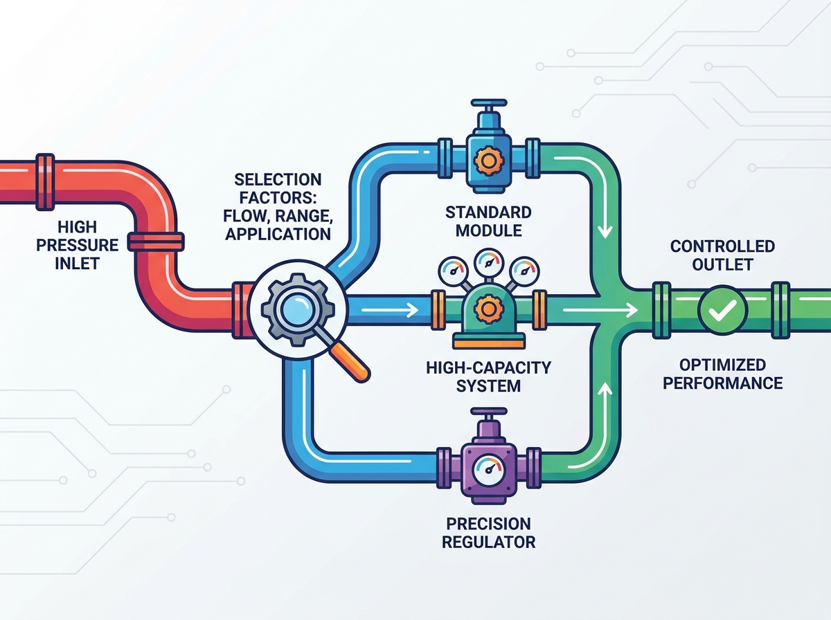
Selecting the right gas pressure reduction unit is a strict mathematical, chemical, and thermodynamic matching process. It is never a generic pipe-fitting exercise. You must follow a logical decision tree to ensure safety and efficiency.
First, define your exact gas and flow parameters. Second, select the correct architecture and calculate your required Cv. Third, determine your staging needs based on SPE tolerances. Finally, select materials based on chemical compatibility and verify performance via manufacturer flow curves.
Take the following next steps to finalize your system design:
Gather precise P1, P2, temperature, and flow rate data for your specific process.
Identify the chemical properties and purity requirements of your gas media.
Consult with a specialized application engineer to review your calculations.
Utilize manufacturer sizing software to verify your chosen Cv and flow curve performance.
A: Pipe size only indicates the physical connection. The Flow Coefficient (Cv) measures the internal orifice's capacity to pass a specific volume of gas at a specific pressure drop. Matching pipe size often leads to oversizing, causing erratic control and premature wear.
A: A two-stage unit is mandatory when drawing from a decaying source, like a high-pressure gas cylinder. It absorbs the fluctuating inlet pressure, preventing the Supply Pressure Effect (SPE) from altering your critical downstream delivery pressure.
A: Freezing is caused by the Joule-Thomson effect. When highly pressurized gas rapidly expands through the regulator orifice, it absorbs heat, causing a severe temperature drop that can freeze ambient moisture on the unit's exterior or embrittle internal seals.
A: Creep is usually caused by debris preventing the seat from closing fully. Prevent it by installing an inline micron filter immediately upstream of the unit. Additionally, ensure you specify the correct seat material for your specific gas and pressure range.
A: No. Self-relieving regulators vent excess pressure directly into the surrounding atmosphere. For flammable, toxic, or hazardous gases, you must use a non-relieving design paired with a safely routed external pressure relief system.


