
Views: 0 Author: Site Editor Publish Time: 2026-07-24 Origin: Site


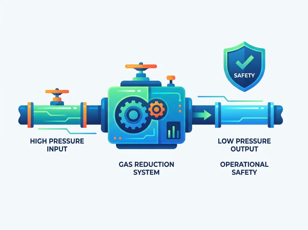
Managing high-pressure industrial gases presents inherent, high-stakes risks. The catastrophic potential of overpressure events, fugitive emissions, and equipment failure requires rigorous engineering controls. Facilities constantly balance the need to maintain high-throughput operational efficiency with the strict necessity of adhering to increasingly stringent Health, Safety, and Environmental (HSE) regulations. Without reliable pressure control, pipelines can rupture, and explosive atmospheric conditions can develop rapidly. Implementing a modern Gas Reduction System serves as the critical engineering control required to stabilize pressure, mitigate hazard exposure, and ensure continuous, safe operations. By stepping down high transmission pressures to safe utilization levels, these systems act as the primary barrier protecting downstream infrastructure and personnel. Upgrading legacy infrastructure to modern standards eliminates the guesswork from pressure management and provides a verifiable layer of protection against process deviations.
Risk Mitigation: Properly specified gas pressure reduction equipment prevents downstream overpressure, directly reducing the risk of pipeline ruptures and explosive atmospheric conditions.
Regulatory Compliance: Automated reduction systems provide the verifiable pressure control and emission reduction data required for Process Safety Management (PSM) and environmental audits.
System Reliability & Resiliency: Integrating redundant safety mechanisms (e.g., active/monitor regulators, dual-run skids) ensures uninterrupted energy supply while protecting downstream instrumentation.
Implementation Reality: Successful deployment requires accounting for physical phenomena like the Joule-Thomson effect (temperature drop) and acoustic vibration during the system sizing phase.
A safe gas handling environment is defined by the ability to maintain pressures strictly within the Maximum Allowable Operating Pressure (MAOP) limits of all downstream equipment. Achieving this requires robust systems designed to handle dynamic flow conditions without compromising safety integrity. Facilities handling natural gas, hydrogen, or specialized chemical gases must engineer their letdown stations to anticipate worst-case scenarios, including sudden downstream valve closures or upstream supply spikes.
Pressure surges occur in industrial pipelines due to sudden changes in demand, valve closures, or upstream supply fluctuations. When a high-pressure wave travels through a pipeline, it can exceed the design limits of downstream components, leading to catastrophic failure. A well-engineered Gas Reduction System acts as the primary barrier, absorbing these upstream fluctuations to deliver a stable, safe downstream pressure. The system dampens the kinetic energy of the gas, ensuring that sensitive downstream instruments, burners, and reactors receive a consistent feed.
Engineers utilize Process Hazard Analysis (PHA) and Layer of Protection Analysis (LOPA) to define the required safety integrity level (SIL) for pressure protection layers. These analyses dictate the necessary redundancy and fail-safe mechanisms required to prevent overpressure scenarios from escalating into major incidents. Implementing LOPA involves several distinct phases:
Identifying the specific hazard scenario, such as a regulator failing in the wide-open position.
Determining the unmitigated consequence frequency based on historical failure rates.
Assigning independent protection layers (IPLs), such as active monitors or slam-shut valves.
Calculating the mitigated event frequency to ensure it falls below the corporate risk tolerance threshold.
A fundamental operational safety principle involves using the minimum possible pressures for any given process to limit potential leak energy. Operating at lower pressures reduces the volume and velocity of gas that could escape during a containment failure. Precision regulation allows facilities to operate closer to these minimum thresholds without risking flow starvation. When operators trust the accuracy of their pressure control, they no longer need to artificially inflate setpoints to buffer against pressure droop.
By tightening the control band, a well-designed system reduces the overall hazard footprint. This approach minimizes the stress on piping networks and lowers the severity of potential fugitive emissions, contributing to a safer working environment. Lower operating pressures also reduce the mechanical fatigue on pipe threads, flanges, and gaskets, extending the operational lifespan of the entire distribution network.
Designing a pressure letdown station requires careful selection of architectural components. Facility engineers must evaluate various solution categories to build a system that meets both flow demands and safety requirements. A standard skid typically incorporates filtration, heating, primary regulation, secondary safety regulation, and overpressure protection.
The primary worker regulator handles the day-to-day pressure reduction tasks, modulating flow to meet downstream demand. The active monitor regulator serves as a redundant safety device installed in series with the worker. Under normal conditions, the monitor remains wide open, allowing the worker to control the pressure. This setup is standard practice in high-capacity natural gas transmission and distribution networks.
The fail-safe logic dictates that if the primary worker fails in the open position, the downstream pressure will begin to rise. The active monitor senses this increase and automatically assumes control, regulating the pressure to a slightly higher, but still safe, setpoint. This configuration ensures continuous operation without venting gas to the atmosphere.
Component Role | Normal Operation State | Failure Mode Response | Primary Benefit |
|---|---|---|---|
Worker Regulator | Actively modulating flow | Fails open (typically) | Precise daily pressure control |
Active Monitor | Wide open (monitoring) | Takes over regulation | Zero-downtime redundancy |
Standby Monitor | Closed (waiting) | Opens to regulate | Protects against worker failure |
Slam-shut valves provide the ultimate mechanical failsafe against overpressure or underpressure events. These devices rapidly isolate the gas flow when pressure deviates beyond pre-set limits, physically blocking the gas path to protect downstream assets. They require manual resetting after an event, ensuring operators investigate the cause of the anomaly before resuming flow. The manual reset is a critical administrative control that prevents the system from automatically restarting into a hazardous condition.
Mechanical slam-shut valves offer significant advantages over traditional pressure relief valves (PRVs). While PRVs vent hazardous gases to the atmosphere to relieve pressure, slam-shut valves contain the gas within the pipeline. This containment is vital for toxic or highly flammable gases and aligns with modern environmental goals to reduce fugitive emissions. Venting high-pressure gas also creates extreme noise hazards, which slam-shut valves completely avoid.
Modern industrial gas reduction skids integrate seamlessly with ambient gas sensors. These sensor networks detect toxic, flammable, or oxygen-depleting/enriching leaks in the immediate vicinity of the pressure letdown station. Early detection is vital for preventing localized incidents from escalating into facility-wide emergencies. Sensors are typically calibrated to trigger alarms at specific Lower Explosive Limit (LEL) percentages.
When a hazard is detected, the system utilizes feedback loops and emergency shutdown (ESD) interlocks to automatically isolate the gas flow. This automated response removes the reliance on human intervention during the critical first seconds of a leak, significantly enhancing overall site safety. The ESD system can trigger pneumatic or electric actuators to close main isolation valves upstream of the reduction skid.
Procurement and engineering teams must evaluate competing systems using rigorous technical criteria. Selecting the right equipment requires balancing flow requirements, material science, and system architecture. Off-the-shelf solutions rarely suffice for complex industrial applications; custom engineering is often required to match the specific thermodynamics of the process gas.
Accurately calculating the required flow coefficient (Cv) is critical for system sizing. The Cv value determines the regulator's capacity to pass gas at a specific pressure drop. Incorrect sizing leads to severe operational issues and safety risks. Engineers must calculate the Cv for minimum, normal, and maximum flow conditions to ensure the selected valve can handle the entire operational envelope.
Oversized regulators operate too close to their closed position, causing hunting, instability, and premature wear on internal components. Conversely, undersized regulators experience choked flow and cannot meet downstream demand, leading to process starvation and potential safety trips. Precise sizing ensures stable control across the entire flow range. When gas reaches sonic velocity within the valve body (choked flow), further decreases in downstream pressure will not increase the flow rate, creating a hard limit on system capacity.
The chemical composition of the gas dictates the metallurgy of the gas pressure reduction equipment. Standard carbon steel may suffice for clean, dry natural gas, but aggressive media require specialized alloys. Evaluating NACE-compliant materials is essential to prevent sulfide stress cracking and hydrogen embrittlement in sour gas environments. NACE MR0175 standards dictate strict hardness limits for metals exposed to hydrogen sulfide.
Alternative and renewable gases, such as Renewable Natural Gas (RNG), introduce unique challenges. RNG often carries trace contaminants like siloxanes, moisture, and carbon dioxide. These impurities necessitate special material considerations, such as stainless steel construction and advanced elastomer selection, to prevent rapid degradation and ensure long-term reliability. Siloxanes, in particular, can precipitate out of the gas stream and form abrasive silica deposits on valve trims.
Gas Type | Primary Contaminant Risk | Recommended Metallurgy | Elastomer Consideration |
|---|---|---|---|
Dry Natural Gas | Particulates, pipeline rust | Carbon Steel (WCB) | Nitrile (Buna-N) |
Sour Gas (H2S) | Sulfide stress cracking | NACE Compliant Steel / 316 SS | FKM (Viton) or specialized blends |
Renewable Natural Gas | Siloxanes, Moisture, CO2 | 316 Stainless Steel | Low-temperature Nitrile or PTFE |
Hydrogen | Hydrogen embrittlement | 316/316L Stainless Steel | High-density polymers |
Facility resiliency relies heavily on the layout configuration of the pressure letdown station. Dual-run (worker/standby) regulator skid configurations provide significant benefits over single-run setups. If one run requires maintenance or fails, the standby run automatically takes over, ensuring zero-downtime operations. The standby run is typically set to a slightly lower pressure than the primary run, allowing it to remain closed until the primary run fails or cannot keep up with demand.
Bypass valve piping layouts are also critical for safe manual system overriding during emergency maintenance cycles. A properly designed bypass allows operators to maintain flow manually while isolating the main regulators for repair, minimizing process disruption while maintaining safety protocols. Operating a manual bypass requires high skill and constant monitoring, as the operator acts as the physical pressure regulator.
Smart positioners and digital pressure transmitters provide real-time operational data, transforming passive mechanical systems into active control nodes. This telemetry allows operators to monitor pressure trends, valve positions, and diagnostic alerts from a central control room. Utilizing protocols like HART or Modbus, these devices feed directly into the facility's SCADA system.
Remote monitoring capabilities remove personnel from hazardous areas during routine pressure checks. By reducing the need for physical inspections, facilities lower the risk of exposing workers to high-pressure environments and potential leak sources. Predictive maintenance algorithms can analyze valve travel data to identify wear before a catastrophic failure occurs.
The technical features of industrial gas reduction systems directly influence tangible business and safety outcomes. Proper implementation aligns operational efficiency with strict regulatory compliance. Facilities that invest in high-quality pressure control infrastructure experience fewer safety incidents and smoother regulatory audits.
Documented pressure reduction capabilities satisfy OSHA PSM requirements, EPA risk management plans, and international HSE guidelines. Facilities must prove that their pressure control systems can reliably prevent catastrophic releases and protect downstream infrastructure. OSHA 1910.119 mandates strict mechanical integrity programs for equipment handling highly hazardous chemicals.
Standard-aligned documentation simplifies safety audits and demonstrates a proactive approach to risk management. By maintaining rigorous records of system design, maintenance, and testing, facilities reduce the likelihood and consequences of unplanned atmospheric releases. Inspectors look for clear evidence that relief valves and slam-shuts are tested at their required intervals.
Upgrading from older, bleed-to-atmosphere pneumatic controllers to zero-emission gas reduction systems supports corporate Greenhouse Gas (GHG) reduction targets. Traditional pneumatic devices continuously vent gas as part of their normal operation, contributing significantly to a facility's carbon footprint. Across a large facility, hundreds of these small pneumatic devices can vent massive volumes of methane annually.
Modern systems utilize instrument air or electric actuation to eliminate these continuous emissions. This transition is vital for environmental compliance and demonstrates a commitment to sustainable industrial practices. Self-contained pilot-operated regulators also offer a zero-emission alternative, as they bleed gas downstream into the lower-pressure system rather than to the atmosphere.
The ROI of redundant safety systems becomes evident when they prevent catastrophic downstream equipment damage. A single overpressure event can destroy sensitive instrumentation, rupture valves, and halt production for extended periods. The cost of replacing a blown boiler or ruptured heat exchanger far exceeds the initial investment in a dual-run regulator skid.
Stable pressure control extends the lifecycle of downstream valves, burners, and instrumentation. By eliminating pressure spikes and flow instability, the reduction system reduces mechanical stress on the entire pipeline network, lowering long-term maintenance costs. Burners operate more efficiently when supplied with a constant pressure, improving overall combustion metrics.
Installing and commissioning high-pressure systems involves specific engineering challenges. Addressing these implementation realities is necessary to ensure long-term reliability and safety. Field engineers must account for thermodynamics, fluid dynamics, and human factors during the design phase.
Significant pressure reduction causes a corresponding drop in gas temperature, known as the Joule-Thomson effect. For natural gas, the temperature typically drops about 7°F for every 100 psi of pressure reduction. This rapid cooling can freeze any moisture present in the gas or cause hydrate formation, blocking the valve and halting flow. Severe freezing can also cause external ice buildup, which can lock the mechanical linkages of the regulator.
Mitigation strategies involve adding heat prior to the reduction stage. Specifying line heaters, catalytic heaters, or heat tracing prevents valve freezing and hydrate blockages. Proper thermal sizing ensures the gas remains above its dew point throughout the pressure letdown process. Engineers must calculate the exact heat load required based on the maximum pressure drop and maximum flow rate.
Excessive aerodynamic noise at the reduction valve presents severe safety risks, including hearing damage for personnel and structural fatigue for the piping system. High-velocity gas flow generates intense vibration that can degrade welds and loosen fittings over time. Noise levels above 85 dBA require mandatory hearing protection programs and limit personnel exposure times.
Solutions for managing noise and vibration include specifying noise-attenuating trims within the regulator body. These specialized trims break the large gas flow into many smaller flow streams, shifting the noise frequency higher and reducing overall sound pressure. Additionally, utilizing thicker pipe schedules and applying acoustic insulation around the letdown station can significantly reduce the ambient noise levels to safe regulatory limits.
Rigorous SOPs are necessary for commissioning, routine maintenance, and emergency bypass operations. Operators must have clear, step-by-step instructions to interact safely with high-pressure equipment. Executing a safe bypass operation requires strict adherence to a sequence of valve movements to prevent pressure spikes.
Verify the downstream pressure requirement and ensure the manual bypass valve is fully closed.
Slowly open the upstream isolation valve to pressurize the bypass line.
Gradually crack the manual bypass valve while closely monitoring the downstream pressure gauge.
Once flow is established through the bypass, slowly close the main line isolation valves to isolate the regulator skid.
Bleed the trapped gas from the isolated skid before commencing maintenance.
Establishing a clear "DOs and DON'Ts" safety checklist for field operators is critical. Emphasize the importance of operator training on the specific failure modes of the chosen equipment. Understanding how the system reacts during a failure ensures personnel can respond appropriately and safely.
A properly engineered gas reduction system is not just a functional requirement for flow control, but the foundational element of a facility's process safety architecture. Decision-makers must prioritize vendors who offer comprehensive system sizing, metallurgical expertise, and integrated safety redundancies over lowest initial cost.
Conduct a site-wide pressure audit to identify aging or undersized letdown stations.
Review current PHA and LOPA documentation to ensure existing pressure protection layers meet required SIL ratings.
Consult with a specialized pressure control engineer to evaluate the feasibility of upgrading to zero-emission, dual-run skids.
Implement a strict preventative maintenance schedule for all slam-shut valves and active monitors.
A: The primary function is to safely step down high-pressure gas from transmission or distribution levels to lower, stable pressures required for safe utilization by downstream equipment and processes.
A: A slam-shut valve physically isolates and stops the gas flow when pressure limits are exceeded, containing the gas within the pipe. A pressure relief valve vents excess pressure to the atmosphere to protect the system.
A: Regulators freeze due to the Joule-Thomson effect, where a significant pressure drop causes a rapid decrease in gas temperature, freezing moisture or forming hydrates. Pre-heating the gas prevents this phenomenon.
A: Inspection intervals depend on usage, gas cleanliness, and regulatory requirements. Typically, visual inspections occur monthly, while comprehensive internal maintenance and testing are performed annually or bi-annually.
A: An active monitor configuration is a redundant setup using two regulators in series. The primary worker controls pressure, while the monitor remains wide open, ready to take over if the worker fails open.
A: Modern systems reduce emissions by replacing older, continuous-bleed pneumatic controllers with zero-emission designs, electric actuators, or instrument-air-driven components, preventing routine venting of methane.
A: Gases containing impurities like moisture, CO2, and H2S require selecting corrosion-resistant materials, such as NACE-compliant stainless steel, and specialized elastomers to prevent equipment degradation and ensure reliability.


