
Views: 0 Author: Site Editor Publish Time: 2026-07-24 Origin: Site


Handling high-pressure natural gas in industrial environments carries massive operational stakes. Imprecise pressure reduction leads directly to catastrophic equipment failure, severe safety hazards, and costly unplanned downtime. Industrial facilities face a constant mechanical challenge. They must manage highly fluctuating inlet pressures from cross-country transmission lines while strictly maintaining stable, compliant, and safe outlet pressures. Sensitive downstream industrial processes demand absolute stability. Power generation turbines, chemical processing reactors, and heavy manufacturing burners rely on exact pressure parameters to function safely and efficiently. The industry has rapidly shifted away from traditional, built-in-place field stations. Facilities now rely on engineered-to-order, modular solutions. A High Pressure Natural Gas Regulating Skid represents the modern standard for mitigating risk. These packaged units accelerate deployment timelines and ensure strict regulatory compliance across complex industrial sites.
Deployment Efficiency: Packaged, modular pressure reducing skids drastically reduce on-site installation time, civil engineering footprints, labor costs, and field-welding risks compared to traditional stick-built stations.
Critical Sizing Metrics: Accurate specification requires precise analysis of maximum/minimum flow rates, inlet/outlet pressure differentials, and gas specific gravity to prevent regulator hunting or capacity bottlenecks.
Non-Negotiable Safety: Industrial compliance mandates robust overpressure protection, typically achieved through active/monitor regulator configurations and emergency slam-shut valves.
Achieving stable downstream pressure is the primary mechanical objective for any gas conditioning system. This stability must hold regardless of upstream pipeline fluctuations or sudden changes in downstream demand. A well-engineered pressure reducing skid meets strict flow capacity demands without hesitation. It prevents sudden pressure drops that could starve industrial burners or cause flameouts. Gas turbines and chemical feedstock lines require uninterrupted, stable flow to prevent automated shutdown sequences. Zero-leakage performance forms the baseline for operational success and site safety. Facilities must adhere strictly to local and international safety standards. Compliance with ASME, API, and NFPA codes dictates the design, fabrication, and testing of these critical systems. Engineers must account for dynamic flow conditions, ensuring the regulating valves respond instantly to load variations without overshooting the setpoint.
Field experience shows that improper pressure control damages downstream instrumentation. When a regulator fails to lock up during zero-flow conditions, pressure creeps downstream. This creep blows out sensitive pressure transmitters and damages low-pressure burner trains. A properly designed skid utilizes tight-shutoff regulators with soft elastomeric seats to guarantee zero leakage at no-load conditions. The success of the entire plant often hinges on the reliability of this single pressure boundary.
Different industrial sectors demand highly specific pressure control capabilities. Each application presents unique operational challenges and flow profiles.
Power Generation: High-efficiency gas turbines require precise fuel gas conditioning. These turbines demand ultra-stable pressure control, often within a 1-2 psig tolerance. Rapid response times are necessary to handle sudden load changes during peak power demand periods.
Heavy Manufacturing & Processing: High-demand thermal processes rely on consistent gas delivery. Glass manufacturing, steel production, and chemical synthesis require exact thermal inputs to maintain product quality. Fluctuations in gas pressure directly alter the air-to-fuel ratio in industrial furnaces.
Transmission & Midstream Gates: Intermediary pressure reduction is a fundamental requirement. Systems drop pressure from cross-country transmission pipelines operating at 1200 psig down to 300 psig. They feed this conditioned gas into local utility distribution networks safely.
In power generation, the regulating skid must often integrate with gas heating systems. Turbines require the gas to be delivered at a specific superheat temperature to prevent liquid fallout in the combustion chambers. Heavy manufacturing facilities often experience highly cyclical loads. A batch furnace might demand maximum flow for two hours and then drop to pilot flow. The regulating skid must handle this massive turndown ratio without losing control stability.
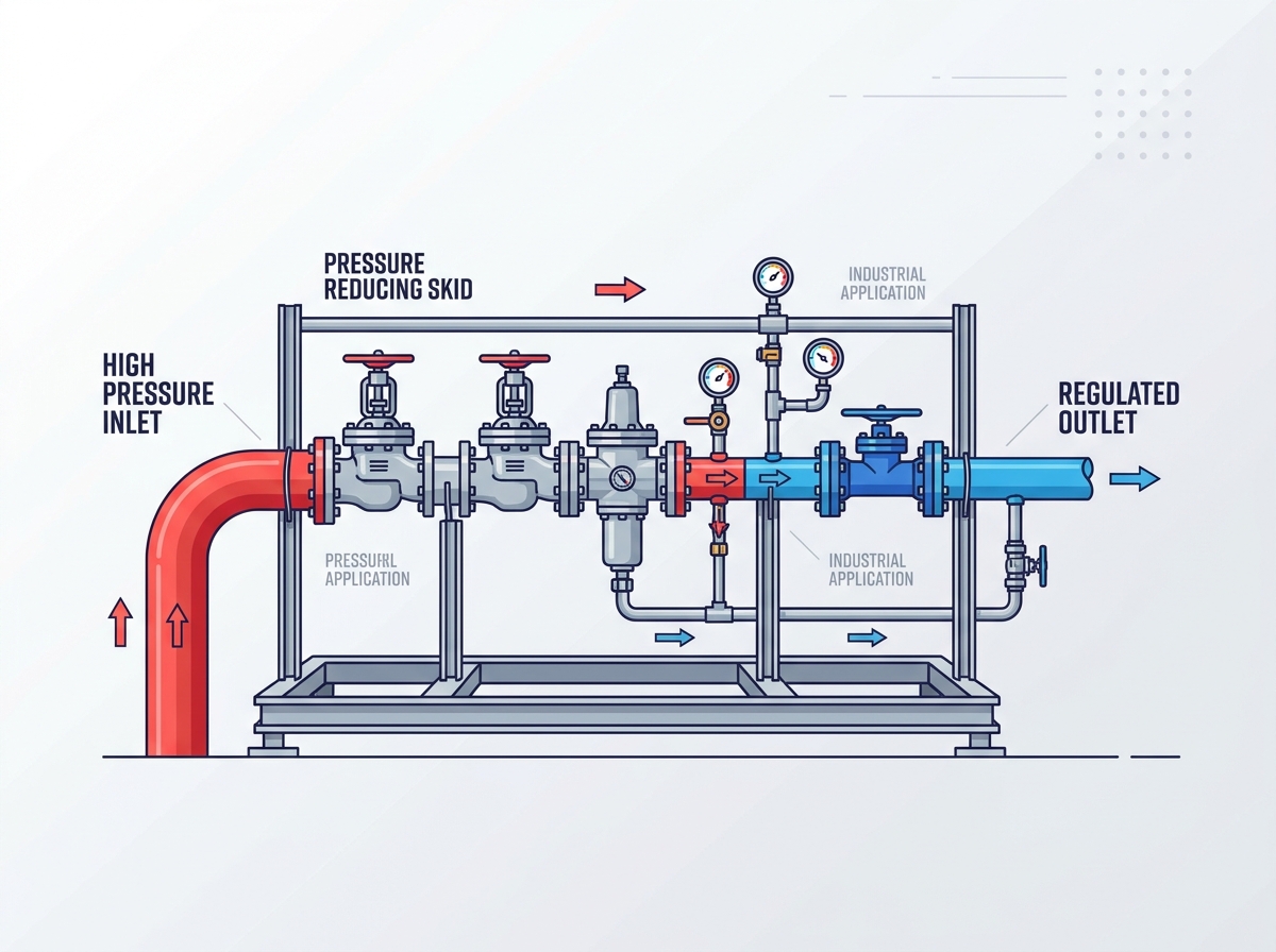
Modular skids offer an optimized, highly compact footprint. Engineers utilize advanced 3D modeling software to design structural steel-framed units. This approach minimizes wasted space and optimizes pipe routing. It contrasts sharply with the sprawling, often chaotic layout of field-routed piping. A traditional high pressure gas station often consumes excessive real estate, requiring massive concrete foundations and extensive fencing. Modular skids provide superior relocation capabilities. Facilities can easily transport, upgrade, or relocate these units using standard heavy-lift equipment. As facility demand patterns evolve, the modular infrastructure adapts without requiring complete demolition and reconstruction.
Consider a facility expanding its boiler capacity. A field-constructed station would require weeks of trenching, pipe fitting, and welding on-site. A modular skid arrives on a flatbed truck, drops onto a pre-poured pad, and bolts directly to the inlet and outlet headers. This plug-and-play functionality drastically reduces site congestion. It keeps hazardous construction activities away from operating plant areas.
Factory-controlled manufacturing delivers unmatched mechanical reliability. Fabrication facilities execute rigorous quality control protocols that are impossible to replicate in the field. Technicians perform 100% X-ray weld verification on high-pressure joints. Non-destructive testing, including magnetic particle and dye penetrant inspections, ensures structural integrity. Hydrostatic testing pushes the piping to 1.5 times its maximum allowable working pressure. Factory Acceptance Testing validates dynamic performance before shipment. On-site fabrication faces unpredictable environmental variables. Rain, wind, and limited tool access compromise weld quality. Factory environments eliminate these variables entirely, ensuring every weld meets ASME Section IX standards.
During a Factory Acceptance Test, technicians flow compressed air or nitrogen through the skid. They stroke the valves, verify lock-up pressures, and trip the slam-shut mechanisms. This controlled environment allows engineers to tune the PID loops and adjust spring ranges before the unit ever sees live natural gas. Field-built stations require this tuning to happen during live commissioning, introducing significant safety risks.
Installing a ready-to-run skid reduces field labor significantly. It minimizes the need for complex hot-work permits and confined space entries. Site disruption drops to near zero. Executing extensive field-built piping works requires massive coordination between welders, pipefitters, and civil contractors. Civil engineering requirements shrink drastically when using modular frames. Facilities pour a simple, flat concrete pad instead of complex, multi-tiered foundations with embedded pipe supports. This streamlined approach accelerates project commissioning and reduces the overall project schedule by months.
Evaluation Metric | Modular Regulating Skid | Field-Constructed Station |
|---|---|---|
Footprint Optimization | Compact, 3D-modeled layout on a single steel base | Sprawling, inefficient piping routes requiring large plots |
Quality Assurance | Factory-tested (100% X-ray, Hydrostatic, FAT) | Variable field testing, highly weather dependent |
Installation Timeline | Days to weeks (Plug-and-play flanged connections) | Months of on-site labor, welding, and inspection |
Civil Engineering | Simple flat concrete pad | Complex foundations, trenches, and embedded supports |
Relocation Capability | Easily transportable via crane and flatbed | Permanent installation, requires complete demolition |
Engineers evaluate single-stage versus multi-stage pressure reduction strategies based on process data. The required pressure drop ratio dictates this choice. Multi-stage reduction prevents freezing during severe pressure drops by stepping the pressure down gradually. The worker/monitor setup represents the absolute industry standard for safety. This configuration places active and standby regulators in series. It ensures fail-safe operation under all conditions. If the primary active worker regulator fails open due to debris or diaphragm rupture, the monitor regulator instantly assumes control. This redundancy prevents catastrophic downstream overpressure events that could rupture plant piping.
In a typical worker/monitor setup, the monitor regulator is set slightly higher than the worker. During normal operation, the monitor remains wide open, acting simply as a piece of pipe. When the worker fails and pressure rises to the monitor's setpoint, the monitor pinches down to regulate the flow. This transition happens in milliseconds, completely unnoticed by downstream processes. Some facilities utilize an active/monitor setup where both valves take a portion of the pressure drop, sharing the workload and reducing noise generation.
Slam-Shut Valves provide immediate, mechanical flow isolation. They trigger automatically during critical overpressure or underpressure events. These valves require manual reset, ensuring operators physically investigate the fault before restoring gas flow. Relief valves serve as secondary, or sometimes tertiary, protection. Sizing considerations for relief valves are highly critical. Engineers must route safe venting away from personnel and ignition sources. Proper venting design prevents hazardous gas accumulation within the facility boundaries. The relief valve must be sized to handle the maximum capacity of the failed regulator minus the demand of the downstream system.
The slam-shut valve senses downstream pressure via a dedicated impulse line.
If pressure exceeds the trip point, the internal latch mechanism releases.
A heavy spring drives the valve plug into the seat, stopping all gas flow instantly.
Operators must isolate the skid, vent the trapped gas, and manually re-latch the valve.
Pipeline particulates destroy regulator seats rapidly. Black powder, pipe scale, and welding slag act like sandpaper on elastomeric seals. Knockout drums and coalescing filters sit upstream of the regulators to protect them. They remove compressor oil, dirt, and entrained liquids. Pressure reduction causes drastic temperature drops due to the Joule-Thomson effect. Natural gas temperature drops approximately 7 degrees Fahrenheit for every 100 psi of pressure reduction. This temperature drop leads to hydrate formation and external freezing. Indirect water bath heaters or catalytic heaters counteract this effect. Heating the gas prior to reduction ensures continuous, ice-free operation and protects downstream carbon steel piping from brittle fracture.
Coalescing filters are particularly vital when the gas originates from aging transmission lines. These filters force the gas through tightly woven fiberglass elements. Microscopic liquid droplets merge into larger drops and fall into a lower sump. Automated liquid drains then expel this waste liquid into a slop tank. Without this filtration, liquids would pool in the regulator bodies, causing erratic control and eventual failure.
Many industrial applications require precise custody transfer measurement. In these cases, the unit functions as a Pressure Regulating and Metering Skid. Engineers integrate ultrasonic, Coriolis, or turbine meters directly into the skid piping. SCADA compatibility is mandatory for modern automated facilities. Smart pressure transmitters and RTD temperature sensors feed continuous data to plant control rooms. Remote monitoring capabilities allow operators to track performance, calculate flow totals, and monitor differential pressure across filters. This data drives predictive maintenance schedules, allowing technicians to replace filter elements before they blind off completely.
Ultrasonic meters have become the standard for high-pressure gas measurement. They contain no moving parts, eliminating mechanical wear. They measure the transit time of high-frequency sound waves traveling with and against the gas flow. This technology provides incredible accuracy and massive turndown ratios, capturing both pilot loads and maximum burner demands perfectly.
The structural base frame requires heavy-duty carbon steel members, typically W-beams or thick-walled structural tubing. Lifting lugs facilitate safe crane placement and rigging. Grounding pads prevent static discharge hazards, a critical requirement in hazardous area classifications. Drip pans contain potential liquid fallout from filter blowdowns. Environmental protection options vary heavily by site location. Open-frame designs suit mild climates with minimal precipitation. Extreme outdoor conditions require custom enclosures. Acoustic panels mitigate the severe high-frequency noise generated by pressure reduction. Weatherproof or blast-resistant enclosures protect critical instrumentation from harsh environments, freezing rain, and unauthorized access.
Accurate sizing prevents operational failures and ensures long-term reliability. Engineers must calculate and document the maximum and minimum inlet pressure range. They define the precise required outlet pressure and acceptable deviation tolerances. Defining maximum, minimum, and normal flow rates is the most critical step. Selecting the correct valve trim depends entirely on these flow rates. Oversizing a regulator causes instability and hunting, where the valve plug slams rapidly against the seat. Undersizing chokes the flow and starves downstream processes during peak demand. Precise flow data ensures stable valve positioning, ideally keeping the valve travel between 20% and 60% open across all normal operating conditions.
Engineers utilize specialized sizing software provided by valve manufacturers. They input the gas specific gravity, temperature, and pressure differentials. The software calculates the required flow coefficient (Cv) and predicts the aerodynamic noise generated by the pressure drop. If the predicted noise exceeds 85 dBA, engineers must specify noise-attenuating trim or thicker pipe schedules to protect plant personnel from hearing damage.
Material selection depends heavily on gas composition and the surrounding environment. Carbon steel (ASTM A106 Grade B) suits standard, non-corrosive natural gas applications perfectly. Stainless steel piping (316L) is necessary for highly corrosive coastal environments or offshore platforms. High operating temperatures or the presence of sour gas (H2S) dictate specific metallurgy compliant with NACE MR0175. Primary codes govern all design phases. ASME B31.8 covers Gas Transmission and Distribution Piping Systems. ASME B31.3 dictates Process Piping standards within plant boundaries. ASME Section VIII governs the design, welding, and certification of pressure vessels, including filter housings and knockout drums.
Flange ratings must match the maximum allowable working pressure of the system. A 600# ANSI flange system handles pressures up to 1480 psig at ambient temperatures. Engineers must ensure that all fittings, valves, and instruments match or exceed this pressure rating. Mismatched flange ratings lead to immediate failure during hydrostatic testing and pose severe safety risks.
Spatial misalignment poses a significant installation risk for modular units. Piping mismatches with existing plant infrastructure cause severe delays and require expensive field modifications. Mandating 3D laser scanning of the installation site mitigates this risk entirely. Engineers scan the site prior to skid engineering, capturing exact tie-in coordinates. Utilizing standardized flange connections ensures seamless tie-ins. Accurate spatial data eliminates field modifications during installation, allowing the skid to drop perfectly into place.
Contractors must also verify the load-bearing capacity of the concrete pad. A fully loaded regulating skid, complete with water bath heaters and heavy block valves, can weigh tens of thousands of pounds. Civil engineers must design the pad to handle this static load, plus the dynamic loads generated by gas flow and potential seismic activity.
Improper initial tuning leads to severe operational issues immediately upon startup. Regulator oscillation and pipeline vibration damage equipment and loosen instrumentation fittings. Nuisance tripping of slam-shut valves halts production and frustrates operations personnel. Comprehensive Factory Acceptance Testing prevents these issues. Facilities must require FAT before shipment. Utilizing the manufacturer's certified technicians for Site Acceptance Testing is vital. Expert startup tuning ensures stable operation from day one. Technicians adjust proportional bands and reset times on the controllers to match the specific dynamics of the downstream piping volume.
During startup, technicians must introduce gas slowly. Rapid pressurization causes the slam-shut valves to trip on high pressure transients. Operators crack the bypass valves, slowly building pressure in the downstream header before bringing the main regulators online. This methodical approach prevents shock-loading the diaphragms and ensures a smooth transition to automated control.
Unacceptable plant downtime during maintenance is a major operational risk. Component replacement, filter changes, and mandatory internal inspections must not halt facility production. Specifying dual-run skids mitigates this downtime entirely. A fully redundant configuration allows technicians to isolate one run completely. They depressurize the isolated run safely using dedicated vent valves. The secondary run maintains uninterrupted gas supply to the facility. This redundancy guarantees continuous plant operation and allows for thorough, unhurried maintenance procedures.
Routine maintenance includes inspecting the elastomeric seats for wear, checking diaphragm integrity, and verifying the trip setpoints of the slam-shut valves. Technicians use deadweight testers to apply precise pressure to the impulse lines, ensuring the safety devices trigger exactly at the required setpoint. Documenting these tests is mandatory for regulatory compliance and insurance audits.
A pre-packaged, engineered-to-order regulating skid delivers superior mechanical results. It provides the most reliable and safe solution for industrial pressure control. It outperforms piecemeal field construction in every technical metric, from weld quality to footprint optimization. Decision-makers must prioritize capable manufacturing partners. Select partners offering in-house engineering and ASME-certified welding programs. Demand transparent sizing calculations and robust testing capabilities.
Gather specific site data immediately, including maximum/minimum flow rates, inlet/outlet pressure differentials, and gas composition.
Measure the available footprint and identify any spatial constraints or hazardous area classifications.
Contact a specialized engineering partner to request a preliminary Piping and Instrumentation Diagram.
Review the proposed valve sizing calculations to ensure they match your specific turndown requirements.
Schedule a site visit for 3D laser scanning to guarantee seamless mechanical integration.
A: A traditional station is built on-site with sprawling, field-routed piping, requiring extensive civil works and field welding. A regulating skid is a compact, factory-assembled, and tested modular unit mounted on a steel frame, offering faster installation and superior quality control.
A: Large pressure drops cause severe temperature decreases due to the Joule-Thomson effect. Engineers prevent freezing by installing indirect water bath heaters or catalytic heaters upstream of the regulators to pre-heat the gas before reduction.
A: It is a fail-safe setup placing two regulators in series. The active worker controls pressure. If it fails open, the standby monitor instantly takes over, preventing dangerous downstream overpressure events that could rupture plant piping.
A: Primary governing codes include ASME B31.8 for gas transmission, ASME B31.3 for process piping, and ASME Section VIII for pressure vessels. API and NFPA standards also dictate safety, venting, and fire prevention protocols.
A: A dual-run setup provides complete redundancy. It allows operators to isolate, depressurize, and perform maintenance on one regulating line while the second line continues supplying uninterrupted gas to the facility.


